Jump to:
System Description | Hazards | Approved Users | Documentation | Controls | Recommended Practices | Maintenance | Emergency Procedures
System Description
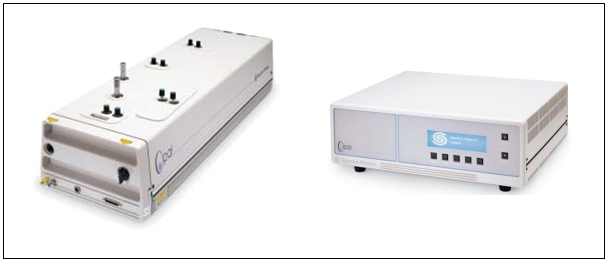
From Spectra-Physics OPAL literature: “The Spectra-Physics Opal® is a synchronously pumped parametric oscillator (SPPO) that delivers tunable femtosecond pulses from 1.1 to 2.25 microns. Opal enhances the versatility of the TsunamiTM ultrafast Ti:sapphire laser by extending its output into the infrared. In addition, Opal also provides frequency- doubled access to the “missing” visible region not accessible by Ti:sapphire alone.” The Opal is located in Room 2135 of the Kim Engineering Building (building #255), on the optics bench farthest from the door. Details regarding the Opal system are given below.
- Vendor: Spectra Physics (Newport Corporation)
- Model #: Opal-1.3
- Serial #: 1130
- Manufactured: December, 1995
- UMD Property Tag #: 118169
- Laser Type: Optical Parametric Oscillator
- Classification: Class IV High Power Laser
Laser Characteristics:
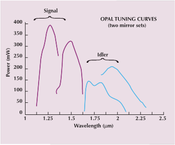
- Wavelength: The Opal can be tuned over a range of wavelengths and produces multiple beams at two output apertures. The standard configuration uses the 1.5 µm optics set and produces a SIGNAL beam that is tunable from 1.35 µm to 1.60 µm. Under this configuration the IDLER beam is 1.60 µm to 2.10 µm. A plot showing the wavelength ranges for both the 1.5 µm and 1.3 µm configurations is shown below.
- Repetition Rate: 82 MHz. The repetition rate is governed by the cavity length, and must be matched the the repetition rate of the 800 nm Ti:Sapphire laser (Tsunami) that serves as the pump
- Pulse Characteristics: < 130 fs, sech2 temporal shape, TEM00 spatial mode, bandwidth > 15 nm, pulses should be nearly transform limited
- Beam Characteristics: beam divergence < 1mrad, beam diameter < 2mm, polarization horizontal (> 100:1)
- Beam Propagation Direction: Signal and idler beams comes out from the side away from Tsunami at a height of 14.5cm above the optical table. The direction of propagation depends on mirrors and other optics placed at output end of Opal. If configured, residue pump beam of 810nm will come out from the side that is facing the Tsunami system.
Hazards
The Spectra-Physics Opal system is an optical parametric oscillator (OPO) capable of generating 250mW@1.5μm with tuning range from 1.35 to 1.60μm at signal beam and from 1.60 to 2.1μm at the idler beam of 150mW. Direct and scattered light of the laser beam is capable of causing permanent damage to eye if left unprotected. Fire hazard is possible if direct or scattered beam hit a combustible material. To ensure the safety of the user and coworkers in the laboratory, the precautions and safe-practices given in the Controls section of this document should be followed.
Approved Users
The principal investigator (PI) for the Spectra-Physics Opal Optical Parametric Oscillator Laser (subsequently referred to as Opal) is Professor Thomas Murphy (subsequently referred to as PI in this document).
Principle Investigator: Professor Thomas E. Murphy (301) 405-0030
Laser Safety Officer: Steve Hand (301) 405-3985
Authorized Users: Updated October, 11 2013
- Ryan Suess
- Mohammad (Mehdi) Jadidi
- Kyowon Kim
- Shanshan Li
- Jeremiah (J.J.) Wathen
Required training:
- Online laser safety training — http://www.des.umd.edu/risk_comm/edu/training.cfm
- UMD Laser Safety training course (schedule via the UMD LSO, Steve Hand, hand@umd.edu)
Visitors may be permitted in the lab while the Tsunami/Opal are operating, but only under the following conditions:
- The visitor has donned the proper eye protection (> OD 7 @ 800 nm
- The visitor has been briefed on the paths of all beams in the lab
- The beam-path is enclosed to the extent possible, with all beams terminated properly (i.e., in folded metal beam dumps or razor-stack beam dumps).
- No adjustments are made to the beam-path while the visitor is present.
- The laser’s cavity must be enclosed while the visitor is present.
Since the Opal requires laser input from the Spectra-Physics Tsunami Mode-Locked Ti:Sapphire Laser please see the standard operating procedure for that laser system and complete requisite training and authorization before proceeding.
Documentation
The Opal User Manual is located on the back shelf nearest the Opal system next to the closed wall cabinets.
Controls
- For alignment purpose, an eyewear of OD>5@800nm is required (safety glasses are located in cabinet immediately to the left when entering 2135 KEB laboratory)
- For normal operation without enclosure, an eyewear of OD>3@1500nm is required (safety glasses are located in cabinet immediately to the left when entering 2135 KEB laboratory)
- Enclose the laser beam path if possible
- All output from OPAL system are invisible except for the residual pump beam. Ensure others in the laboratory are informed of its beam path.
- Maintain the beam height at the default height if possible.
- Move any combustible material away from the beam path
- Maintain a designated rapid egress
- Caution when using combustible gases and liquids in the area of the laser
- Know location of eyewear, documents and related accessories
- Avoid direct exposure to the laser light. The intensity of the beam can easily cause flesh burns or ignite clothing
- Turn off the Tsunami’s pump laser when not in use
- To reduce possibility of eye damage, maintain a high ambient light level in the laser operation area during normal operation.
- Unless for alignment purpose, keep the protective cover on the laser at all times
- Avoid reflective objects such as jewelry, rings, and watches while using the laser
- Use infrared sensor and infrared scope in alignment
- When the Opal cabinet cover is removed, an interlock blocks the input pump beam into the cavity. When performing alignment procedures this interlock needs to be defeated (red lever is flipped to upright position) to allow pump beam into cavity.
Additional Hardware useful for diagnosing the Opal laser system:
- High reflector M7 diagnostic mirror is located in optics cabinet on the East side of 2135 KEB laboratory; it should be clearly marked, handled with care, and placed back in the cabinet when not in use
- Additional mirrors and other parts in black Spectral-Physics box kept in file cabinet next to laser
- 3910 regulator/filter purge unit in file cabinet next to laser
- Suggested Spectrum analyzer: HP70951A Fiber Coupled Spectrum Analyzer, located in movable rack mount cabinet
- High power photodetector: Thorlabs Thermopile Photodetector
- Suggested Autocorrelator: Pulse Check APE Autocorrelator
Recommended Practices
Follow the Operation section in Tsunami SOP before working with the Opal system. Proceed only after the Tsunami system is running normally (e.g., system is mode-locked, has clean (Gaussian) output spectrum, the current supplying the pump diode lasers in the Tsunami system has stabilized (roughly 20 minutes), etc.). Optimal performance of the Opal is achieved with the Tsunami LED bar fully illuminated, its output power is 2W and its bandwidth is approximately 10nm with a center wavelength of 810nm. Set the signal beam wavelength to 1.5μm. Press the button corresponds to “Setup” and then press “Scan Length”. The laser should start lasing when it moves to the right position. Optimize the output power by adjusting M1 and M7, then change the signal wavelength to the desired wavelength and optimize output power again.
Occasionally, the Opal could fail to find the right length required to match the cavity length to that of the Tsunami cavity. In such cases, do not try to realign the system. Instead, check Tsunami output to see if there is any abnormality. Only after checking that the Tsunami system is operating normally, go to the “Diagnostics” menu from the “Main” menu, then select “Manual Control” on the Opal controller. Move the cursor to Motor, turn off the loop, and then move M1 mirror slowly. If necessary, remove the cover of Opal, and place a business card at the point where scattered beams from the crystal are. When the M1 moved to the right location, you will be able to see a green flash on the business card. If all these steps failed, replace the output coupler by high reflector G0380-002 then adjust M1, M7 mirrors and move M1 until you see the green flash. Switch back to output coupler when done.
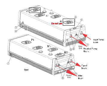
The above figure is a diagram of Opal unit detailing input and output apertures and mirror controls. M1 and M7 are the mirrors that define the ends of the Opal cavity; P1 should only be adjusted during initial alignment. Adjusting P1 without a strongly attenuated input beam and other precautions given in the Opal manual could permanently damage the nonlinear crystal.
The Opal system may be left on for multiple days to maintain system stability if an authorized user is conducting measurements over a prolonged period. Proper beam blocks (components designed specifically for the purpose of blocking and diffusing high optical powers) should always be used in this scenario as a dump for all beams leaving the Opal unit. For information on what constitutes a proper beam block please ask an authorized user or the laboratory PI.
Additional notes and warnings:
- The P1 mirror adjustment is too coarse for optimizing Opal. Since the crystal is small, it is highly possible that you would move the beam to the edge of the crystal, which will damage the crystal if left unnoticed. Do not use P1 adjustment except for initial alignment.
- Check the output wavelength of Opal, if it is off by >3nm, follow appendix C on the manual to recalibrate the grating in Opal.
- If wavelength of < 1500nm is required, the Opal system would have to be purged. Refer to Fig 3-7 in Pg 3-7 of the manual for more detail.
- Fluorescent cards designed for near infrared wavelengths and an infrared viewing scope can be used to view the signal beam leaving the Opal
- The time-bandwidth product of the output pulses from the Opal should be checked with measurements from an autocorrelator and spectrum analyzer. Details regarding the time-bandwidth product for the output signal pulses from the Opal are given in the Opal Manual. This step should be done anytime the Opal has been out of use for an extended period, or before data is to be taken using the Opal.
Maintenance
CAUTION: Unless for planned power outage and temporary relocation, never turn off the Opal power supply. The Opal uses an LBO crystal for its frequency conversion and it’s required that the LBO crystal be maintained at roughly 150 oC at all times to avoid damage.
Opal temperature tuning settings are stored on a PCMCIA card inside the controller box. To prevent loss of this information, the PCMCIA card has a battery on it that need to be replaced every 2-3 years. The specific battery used on this OPAL system is BR2325. Note that the Opal system cannot be turned off when replacing this battery, follow the instruction on appendix D in the manual.
It is recommended to replace the output coupler M1 with a high reflector G0380-002 during alignment process. This mirror is usually kept in the Spectra- physics accessory box in file cabinet next to table 3.
After alignment, be sure to move the waveplate back to its default position.
CAUTION: Do not use Acetone or Methanol for cleaning the crystal. It is recommended that the crystal should not be cleaned unless absolutely necessary. In such case, use a spectrophotometric grade hydrocarbon solvent such as toluene or xylene. Follow the instructions in the manual on how to clean this crystal.
Additional notes:
- For questions regarding maintenance please see authorized users list.
- Please see Maintenance section of the Tsunami SOP for related maintenance and upkeep related to Opal system.
- Service logs for Opal are kept with the Opal documentation and on the PRL shared drive under PRL_Share/Verdi_Tsunami_Opal/
Emergency Procedures
In the case of a medical emergency (e.g., you or a colleague suffer personal injury due to accidental laser exposure) contact UM Emergency (Fire-Police-Rescue) immediately. In the case of non-injury related emergencies, follow standard shut down procedures for the Opal-Tsunami laser system and contact an authorized user. The following table gives relevant emergency contact numbers.
| Name and Description | Contact Information |
| UM Emergency (Fire, Police, Rescue) | #911 |
| Environmental Safety Office | x5-3960 |
| UMD Laser Safety Officer | x5-3985 |
| University Health Center | x4-8172 |
| Workers Compensation Office | x4-8171 |
| Facilities Management | x5-2222 |
| Laboratory PI (T. E. Murphy) | x5-0030 |